
Today I will introduce to you a SLAM algorithm published on IROS in 18 years. Not much to say or write the original text: Shan T, Englot B. Lego-loam: Lightweight and ground-optimized lidar odometry and mapping on variable terrain[C]//2018 IEEE/RSJ International Conference on Intelligent Robots and Systems (IROS). IEEE, 2018: 4758-4765.
First, make a brief introduction to the LeGO-LOAM paper.
Summary
LeGO-LOAM features
1) A lightweight, which can run on embedded platforms
2) Point cloud segmentation to remove noise
3) Real-time 6-degree-of-freedom estimation with ground optimization (utilizing the existence of ground plane in the segmentation and optimization steps)
4) Loopback detection
LeGO-LOAM process:
1) First apply point cloud segmentation to filter out noise
2) Then feature extraction receives feature planes and feature edges
3) Two-step Levenberg-Marquardt optimization method: the plane features extracted from the ground are used to obtain [tz, θroll, θpitch] in the first step, and in the second step, by matching the edge features extracted from the segmented point cloud Get the rest of the transformation [tx,ty,θyaw]
Compared to LOAM, LeGO-LOAM achieves similar or better accuracy while reducing computational overhead.
1 .Introduction
Vision-based methods have many advantages in closed-loop detection, but vision-based methods are highly sensitive to lighting and observation points and are prone to instability. Radar is not sensitive to light.
About ICP:
The most typical method to find the coordinate transformation between two radar scans is iterative closest point (ICP). By finding the correspondence point by point, the ICP iteratively aligns the two sets of points until the stopping criterion is met. When the scan includes a large number of points, the ICP may suffer from excessively high computational costs.
Academia has proposed many variants of ICP to improve its efficiency and accuracy [2].
[3] introduced a point-to-plane ICP variant that matches points with local plane patches.
Generalized-ICP [4] proposed a method of matching two-scan local plane patching.
In addition, some ICP variants use parallel computing to improve efficiency [5]-[8].
Feature-based matching methods require less computing resources by extracting representative features from the environment.
The conditions for becoming a feature: 1) effective matching 2) independent of viewpoint.
The point feature histogram (PFH) [9] and the viewing angle feature histogram (VFH) [10] are methods that use simple and effective techniques to extract these features from the point cloud.
[11] introduced the use of Kanade-Tomasi corner detector to extract common features from point clouds.
A framework for extracting line and plane features from dense point clouds is discussed in [12].
Algorithm for using feature registration for point cloud:
[13] and [14] proposed a key point selection algorithm: perform point curvature calculations in a local cluster, and then use the selected key points to perform matching and position recognition.
[15] Projected the point cloud onto the distance image and analyzed the second derivative of the depth value, and then selected features from points with large curvatures for matching and location recognition.
A plane-based registration algorithm is proposed in [16]. Outdoor environments (such as forests) may limit the application of this method.
The neckline segment (CLS) method of [17] is specially designed for Velodyne lidar. CLS uses points from two consecutive "loops" from the scan to randomly generate lines. Then two line clouds are generated and used for registration. But random generation of lines interferes with this method.
A registration algorithm based on segmentation is proposed in [18]. SegMatch first applies segmentation to the point cloud. Then the feature vector is calculated for each segment based on its feature value and shape histogram. Random forest is used to match fragments from two scans. Although this method can be used for online attitude estimation, it can only provide positioning updates of about 1 Hz.
[19] and [20] proposed LOAM. LOAM performs point features on edge/planar scan matching to find the correspondence between scans. The feature is extracted by calculating the roughness of points in its local area. Select points with high roughness values as edge features. Similarly, points with low roughness values are designated as flat features. Real-time performance is achieved by cleverly dividing the estimation problem between two separate algorithms. An algorithm runs at a high frequency and estimates the sensor speed with low accuracy. The other algorithm runs at low frequencies but returns high-precision motion estimation. The two estimates are fused together to produce a single motion estimate with high frequency and high accuracy. The final accuracy of LOAM is the best effect that only the lidar estimation method can achieve on the KITTI ranging reference site [21].
与此原文有关的更多信息要查看其他翻译信息,您必须输入相应原文
Applicable scenarios of LeGO-LOAM:
1) There is no powerful computing unit (industrial computer).
2) Due to the limited size, many unmanned ground vehicles (UGVs) do not have a suspension. Small UGVs often encounter non-smooth motions, and the acquired data is often distorted, and it is difficult to find a reliable feature correspondence between two consecutive scans. relation.
In the above conditions, when resources are limited, the performance of LOAM will deteriorate. The reasons for the deterioration are as follows:
1) Due to the need to calculate the roughness of each point in the dense 3D point cloud, the feature extraction update frequency on the lightweight embedded system cannot always keep up with the sensor update frequency.
2) Data distortion, operating UGV in a noisy environment also poses a challenge to LOAM. Since the installation location of lidar is usually close to the ground on a small UGV, the sensor noise from the ground may be constant. For example, the distance information of grass may result in a high roughness value. Therefore, unreliable edge features need to be extracted from these points. Similarly, edge or plane features can also be extracted from the points returned by the leaves. These features are generally unreliable for scan matching, because the same blade of grass or leaves may not be seen in two consecutive scans. Using these functions may cause inaccurate registration and large drift.
Based on the above reasons, LeGO-LOAM is proposed to estimate the attitude of UGV in a complex environment. advantage:
1) LeGO-LOAM is lightweight, because it can realize real-time attitude estimation and mapping on embedded systems.
2) Remove the distorted data. After the ground separation, perform point cloud segmentation to discard points that may represent unreliable features.
3) LeGO-LOAM introduces ground optimization because we introduce a two-step optimization pose estimation. The plane features extracted from the ground are used to obtain [tz,θroll,θpitch] in the first step. In the second step, the remaining part of the transformation [tx,ty,θyaw] is obtained by matching the edge features extracted from the segmented point cloud.
4) The ability to integrate loop detection to correct motion estimation drift.
The rest of this article is organized as follows:
Section 2 introduces the hardware used for the experiment.
Section 3 describes the proposed method in detail.
Part 4 introduces a series of experiments in various outdoor environments.
2. System hardware
The measurement range of VLP-16 is up to 100 meters, and the accuracy is ±3 cm. It has a vertical field of view (FOV) of 30° (15°) and a horizontal FOV of 360°. The 16-channel sensor provides a vertical angular resolution of 2°. The horizontal angle resolution varies from 0.1° to 0.4° depending on the rotation rate. Throughout the paper, we choose a scan rate of 10Hz, which provides a horizontal angular resolution of 0.2°.
HDL-64E (in this work through the KITTI data set) also has a 360° horizontal FOV, but it also has 48 channels. The vertical FOV of HDL-64E is 26.9°.
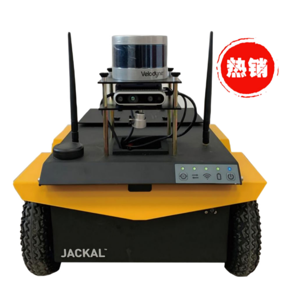
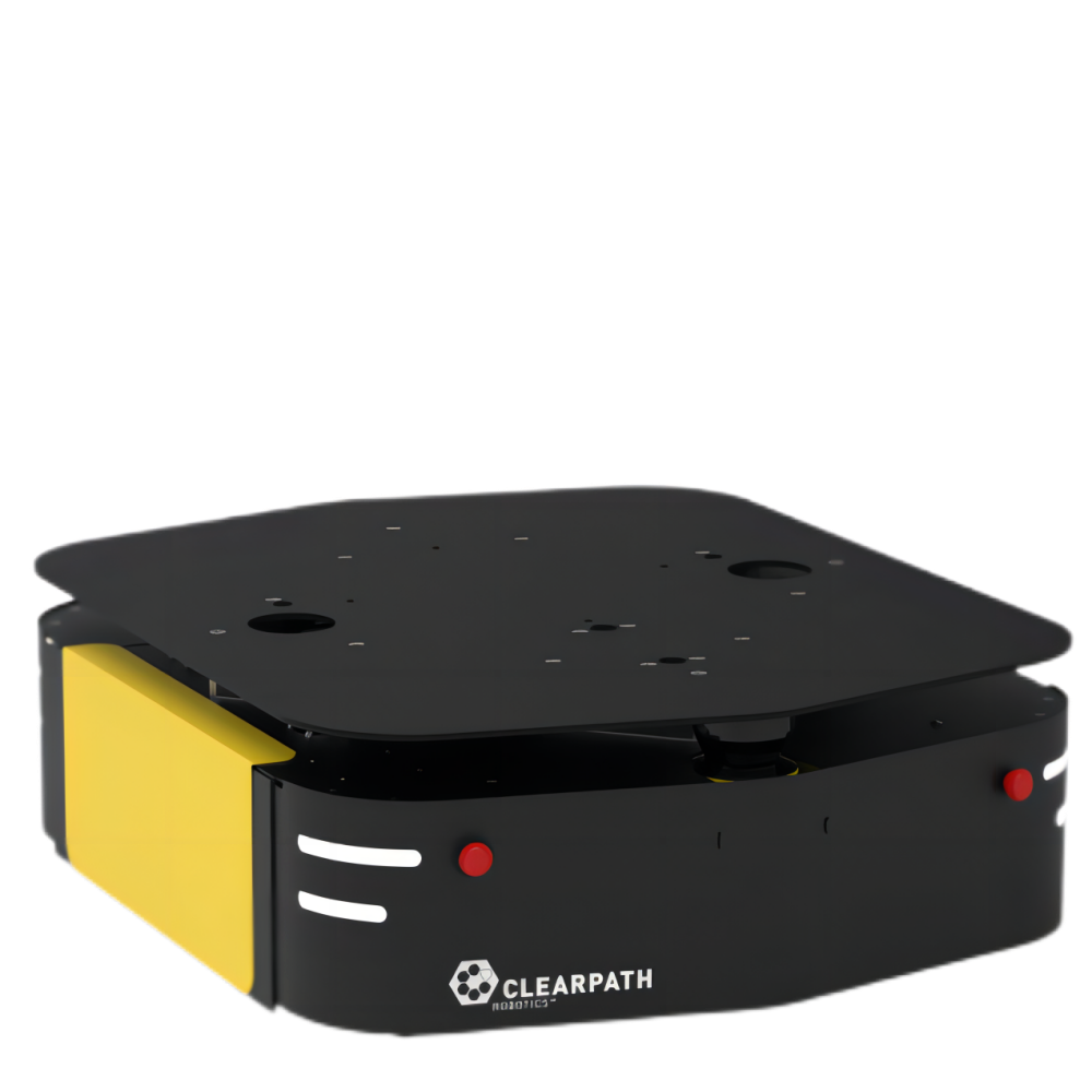
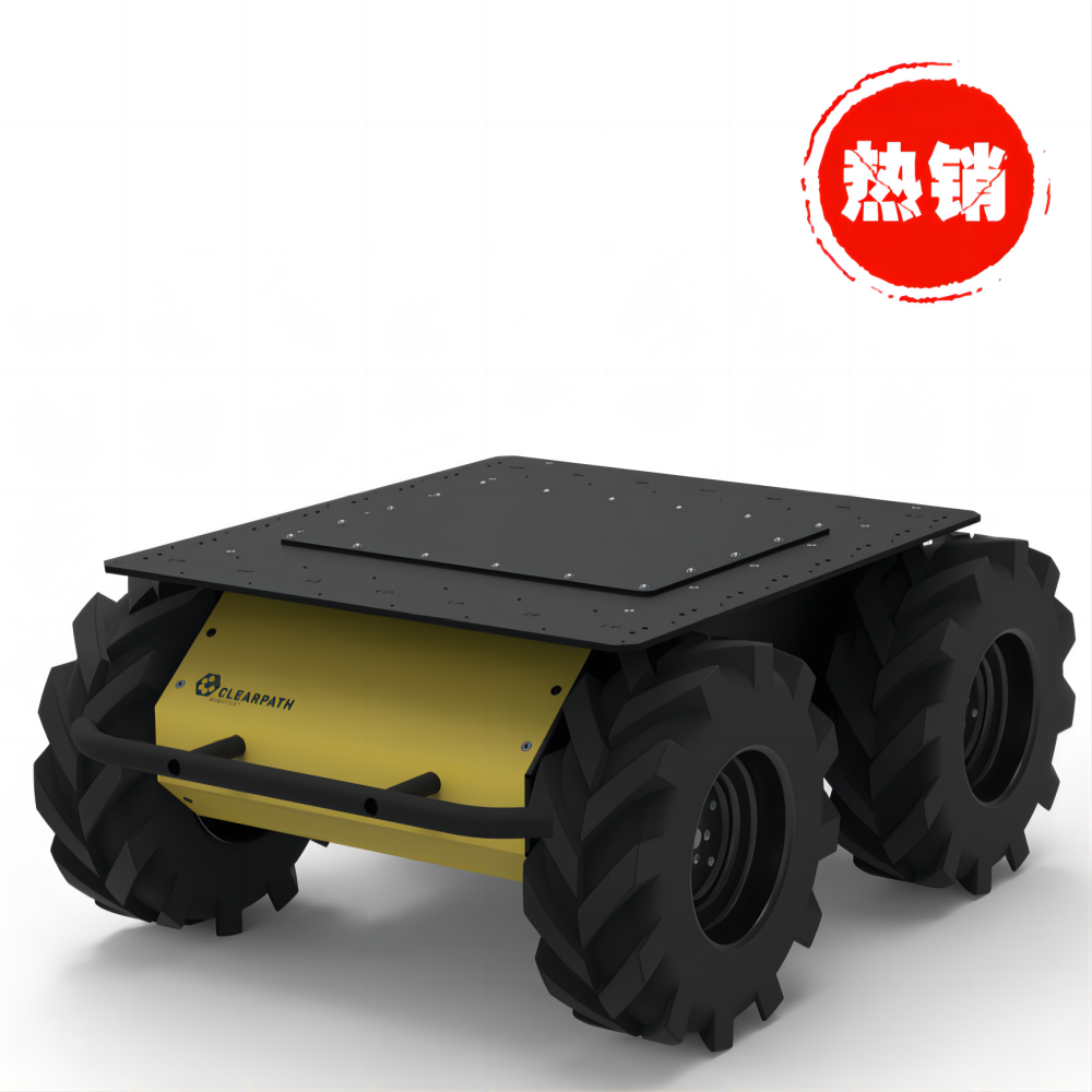
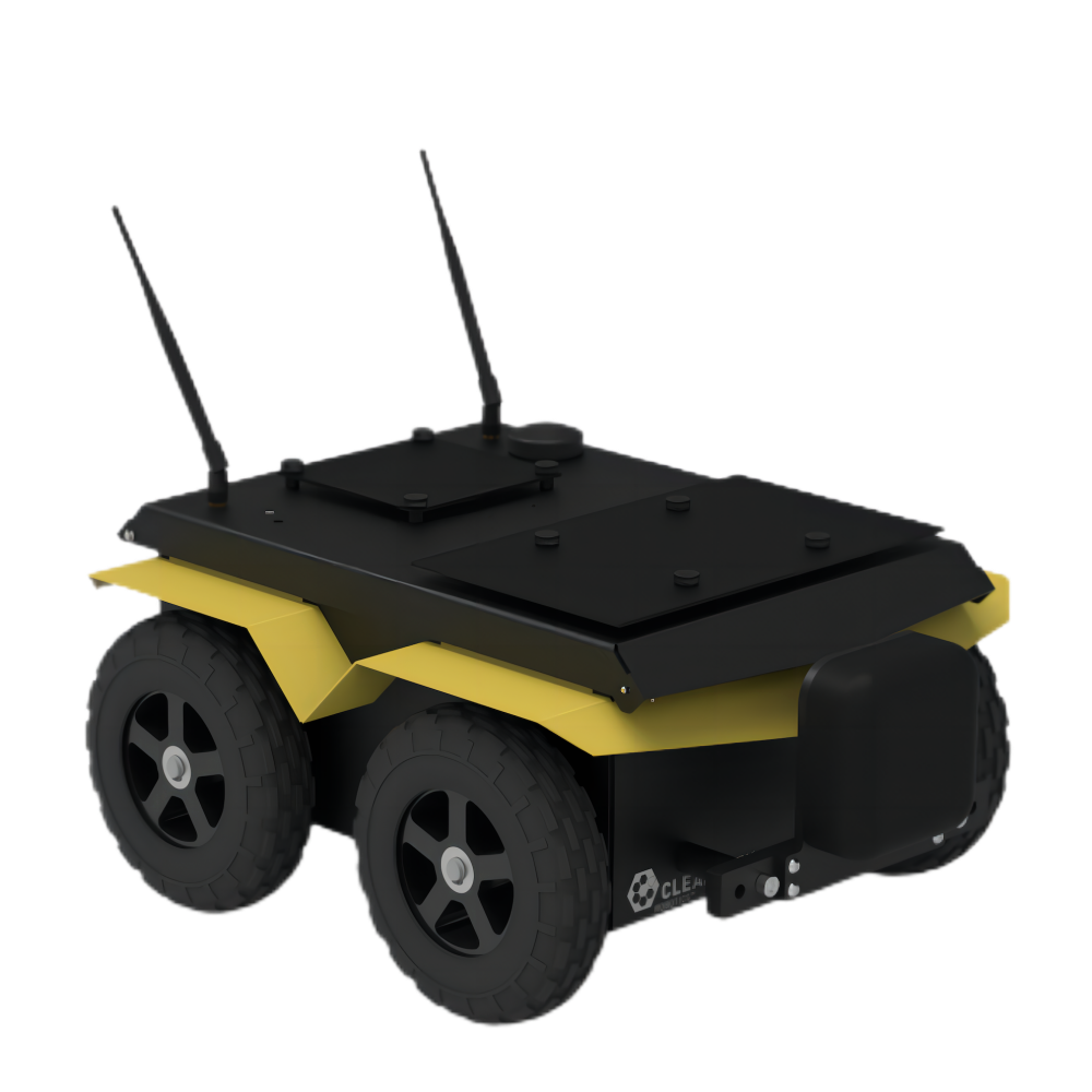
The UGV used in this article is Clearpath Jackal. Powered by a 270 watt-hour lithium battery, the maximum speed is 2.0 m/s, and the maximum payload is 20 kg. Jackal is also equipped with a low-cost inertial measurement unit (IMU), CH Robotics UM6 direction sensor.
The proposed framework is verified on the laptop of Nvidia Jetson TX2 and 2.5GHz i7-4710MQ:
Jetson TX2 is an embedded computing device equipped with ARM Cortex-A57 CPU.
The laptop CPU matches the computing hardware used in [19] and [20], which is the same configuration as in Zhang Ji's paper.
3.Lightweight lidar measurement and mapping
A.System Overview
The outline of the framework is shown in Figure 1.

The point cloud is grouped and clustered, and only points that can represent large objects (such as tree trunks) and ground points are retained (Figure 2(b)):
1) Points from the same cluster will be assigned a unique label. Ground points are a special type of cluster. Applying segmentation to point clouds can improve processing efficiency and feature extraction accuracy.
2) The environment is noisy, and these features of leaves are unreliable. At the same time, in order to improve the speed, we omit the clustering of less than 30 points.
Each point gets three attributes:
1) Its label is used as the base point or segment point,
2) Its column and row index in the distance image
3) Its range value.
C.Feature extraction
The feature extraction process is similar to Zhang Ji's paper [20], but instead of extracting from the original point cloud, it extracts features from ground points and segmented points.
1) Calculate the roughness of each point Pi: Let S be the point set of consecutive points pi in the same row in the range image. Half of the points in S are on either side of pi. In this article |S|=10.
2) In order to extract features uniformly from all directions, the range image is horizontally divided into several equal sub-images.
3) Sort the points in each row of the sub-image according to the roughness value of each point.
4) We use the threshold Cth to distinguish different types of features. C>Cth: edge feature, C<Cth: plane feature.
5) Select nFe feature edges that do not belong to the ground and have the largest c value from each row of the sub-image.
6) Select nFp plane feature points with the smallest c (can be marked as ground or segment points)
7) Fe and Fp and are the set of edge and plane features of all sub-images. As shown in Figure 2(d).
8) Extract the nFe edge features with the largest c from each row in the subgraph, and they do not belong to the ground.
9) Extract nFp plane features with the smallest c from each row in the subgraph. The feature point must be a ground point.
10) The first two steps generate edge set Fe and plane set Fp. The characteristics of Fe⊂Fe,Fp⊂Fp are shown in Figure 2(c).
The feature points and feature planes are extracted twice. The 360° range image is divided into 6 sub-images. The resolution of each sub-image is 300 by 16. Let nFe=2, nFp=4, nFe=40, nFp=80.
D.Radar odometer
Estimate the sensor movement between two consecutive scans:
Find the transformation between two scans through point-to-edge and point-to-surface scan matching. The collection of features from the previous scan
and Find the corresponding features of the midpoint of nFp and nFe.
Improvements to improve the accuracy and efficiency of matching:
1)Label matching:
 and
and the features in are coded with tags,So from
 and
and 于
于 Find the corresponding points with the same label.The right plane point, only in
 Only those marked as ground points will be used to find the corresponding plane piece in
  .
.
对于 中的边缘特征,从
 中寻找对应的边缘线。这种方式提高匹配准确性,缩小了潜在对应特征的数量。
2)两步L-M优化:
两步L-M优化方法,最佳转换T分两步找到:
1)将  中的平面点和
 中对应的特征相匹配,估计得到 [tz,θroll,θpitch]
2)将  中的边缘点和
 中对应的特征相匹配,加上附加条件
[tz,θroll,θpitch] ,得到剩下的 [tx,ty,θyaw] 。
虽然 [tx,ty,θyaw] 也可以放在第一步时进行,但这样准确度不高,得到的结果也不能继续放在第二步中使用。
2个连续scan之间的6自由度变换通过融合 [tz,θroll,θpitch] 和 [tx,ty,θyaw] 获得。
两步L-M优化得到相同的精度,计算时间可以减少约35%(表3)。
E.雷达建图
雷达建图以较低的频率运行,匹配 中的特征到点云地图
 上,以优化位置变换。再用L-M方法得到最后的变换。
LeGO-LOAM的主要区别在于如何存储最终点云图:
保存每个单独的特征集 ,而不是保存单个点云图。
例如, 表示以前所有特征集合的集合。每个
 中的每个特征集合和雷达scan时pose相关联。
通过 得到
得到 有两种方式:
第一种和Zhang Ji论文类似,选择在传感器视野里面的特征点集获得  。选择距离当前传感器位置100m以内的特征集合。选择的特征集合然后变换和融合到单个周围地图
  。
。
第二种,在LeGO-LOAM中集成图优化方法。
1)图的节点:每个特征集合的传感器位姿。
特征集合 被看做为这个节点上的传感器测量数据。
2)雷达建图模型的位姿估计drift很低,假设在短时间内没有drift。通过选择一组近来的特征集合来构成  ,例如
,例如
(其中k表示  的大小)。
的大小)。
3)新节点和  中的已选节点之间加上空间约束(通过L-M优化得到的坐标变换)。
4)用loop closure进一步消除雷达建图的drift。如果用ICP发现当前特征集和先前特征集之间有匹配,则添加新约束。然后通过将姿势图发送到诸如[24](iSAM2)的优化系统来更新传感器的估计pose。
注意,只有第四节(D)中的实验使用此技术来创建其周围的地图。
4.Experiment
Click the link below to display the video:
https://mp.weixin.qq.com/s/8jYMgKpxf11cINgm_LtVgw
5.In conclusion
We have proposed LeGO-LOAM, a light-weight and ground-optimized lidar ranging and mapping method for performing real-time attitude estimation of UGV in complex environments. LeGO-LOAM is light in weight and can be used on embedded systems to achieve real-time performance. LeGO-LOAM also carried out ground optimization, using ground separation, point cloud segmentation and improved L-M optimization. In the process, it is possible to filter out the worthless points that may represent unreliable functions. Two-step L-M optimization can calculate different components of posture transformation separately. The proposed method was evaluated on a series of UGV data sets collected in an outdoor environment. The results show that, compared with the latest algorithm LOAM, LeGO-LOAM can achieve similar or better accuracy. The calculation time of LeGO-LOAM is also greatly reduced. Future work involves exploring its application to other types of vehicles.
6.Xuanwu 2 introduction leaflet


Donghu Robot Laboratory, 2nd Floor, Baogu Innovation and Entrepreneurship Center,Wuhan City,Hubei Province,China
Tel:027-87522899,027-87522877
Robot System Integration
Artificial Intelligence Robots
Mobile Robot
Collaborative Robotic Arm
ROS modular robot
Servo and sensor accessories
Scientific Research
Professional Co Construction
Training Center
Academic Conference
Experimental instruction
Jingtian Cup Event
Business cooperation: 18062020215
18062020215@qq.com
Pre sales technical support:
Tel 13807184032
 |
 |